1.SwinTransformer overview#
Since Transformer has made breakthrough progress in NLP tasks, the industry has been trying to use Transformer in the CV field. Several previous attempts have used Transformer in the field of image classification, but these methods all face two very severe challenges, one is the multi-scale problem, and the other is the problem of computational complexity.
Based on these two challenges, the author of swint proposed a Transformer for hierarchical extraction, and learned features by moving windows. Calculating self-attention in the window can bring higher efficiency; at the same time, through the operation of moving, there is interaction between adjacent windows, which achieves a kind of global modeling ability in disguise, and then solves the above two problems.

Swin Transformer combines the transformer structure with the idea of cnn, and proposes a backbone that can be widely applied to various computer vision fields. It shows good results in data sets of tasks such as detection, classification, and segmentation, and can be applied to many Scenarios that have high requirements for precision. The reason why Swin Transformer can have such a big influence is mainly because after ViT, it has further proved that Transformer can be widely used in the field of vision through its strong performance in a series of visual tasks.
The following table shows the performance of the current swin-t model on 1684X. This article mainly focuses on optimizing the deployment of FP16 and INT8 models.
| prec | time(ms) |
|---|---|
| FP32 | 41.890 |
| FP16 | 7.411 |
| INT8 | 5.505 |
2.Performance Bottleneck Analysis#
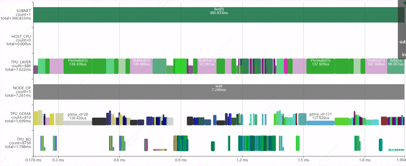
Use the bmprofile tool to visualize the running status of the FP16 model on the 1684X. Here is a block in the model. It can be seen from the figure that a large number of permute (transpose) layers are interspersed among them. On the one hand, it brings a large data handling overhead, on the other hand, it makes the network unable to layergroup, and the parallel effect is poor.
3.Model optimization#
3.1.transpose eliminate#
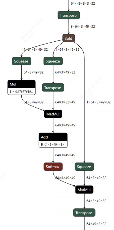
Observe the attention structure in the figure, there are 3 transpose layers. The first transpose layer can be disassembled into two transposes. One is to move the dimension (3) where the QKV is located to the front, and the other is to exchange the order of the dimension (3) where the head is located and the dimension (49) where the patch is located. Since the split operation followed immediately is to split the QKV into three branches, it is not necessary to do the first transpose here, but let it directly split on the original dimension. In this way, the execution order of the second transpose is changed, so that it moves down to the three branches respectively. The reason for this is that in tpu-mlir, the fusion of transpose and adjacent matmul operators is supported, so when transpose moves down to the upper layer of the matmul operator, it can be fused with matmul.
Careful readers may find a problem, the right input of the matmul of QK multiplication already has a transpose, can another transpose be superimposed and merged together? Which transpose is it integrated with? In order to explain this problem, we can analyze it from the picture below.
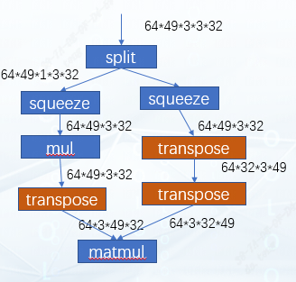
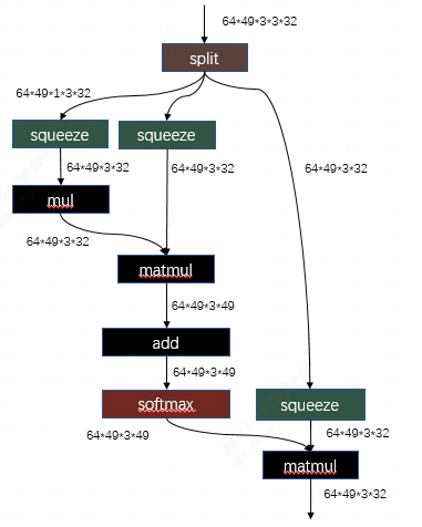
This is the effect we expect to achieve after graph optimization. It can be seen that matmul multiplies the two matrices of 49x32 and 32x49, and 64 and 3 can be regarded as batches. It just so happens that our tpu-mlir supports the optimization of hdim_is_batch. Therefore, for this case, the left and right transposes are eliminated after optimization, and a new transpose will be added at the output position of matmul. After that, this matmul can be Rtrans fused with the remaining transpose on the right. Results as shown below:
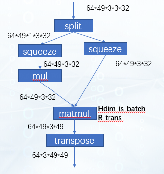
The extra transpose of this output can continue to be moved down to the next matmul. At this time, the network structure is shown in the figure:
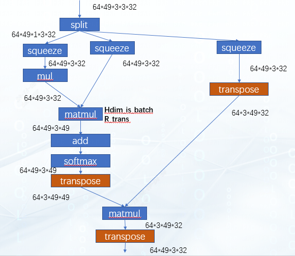
For the second matmul, apply the optimization of hdim_is_batch again to eliminate the transpose layer of the left and right inputs, and then the extra transpose added to the output can just offset the last transpose layer of the network. So far, all transposes have been eliminated.
related code:tpu-mlir/lib/Dialect/Top/Canonicalize/MatMul.cpp
MatmulWithPermuteAndSplit这个pattern就是用于识别swint中的attention结构,并将transpose+split+squeeze的结构进行调整,其目的就是为了让整块结构可以成功的利用我们编译器已有的一系列针对transpose+matmul这个组合的优化。
3.2.better layer-group#
The storage space of the TPU includes Local Memory and Global Memory. The execution of an independent calculation instruction will go through the process of gdma (global → local), bdc, gdma (local → global). During the execution of the model, the operation of gdma is less The better, so that we can use our TPU computing power to a greater extent. Based on this idea, the function of LayerGroup is designed in tpu-mlir. After calculation, LayerGroup can divide multiple calculation instructions into a Group. In a Group, each Op is directly use the data on Local Memory stored by the previous Op. This can reduce the moving out and moving in between every two Ops, thereby reducing the io time. Therefore, the effect of layergroup is often a factor we should consider when optimizing a model.
After completing the optimization work in 3.1, according to the operation logic, the attention should be able to be grouped together, but the actual situation is not the case. As shown in the figure, a part of the attention structure of final.mlir is intercepted here, and each op here is global layer, indicating that there are still optimization points in it.
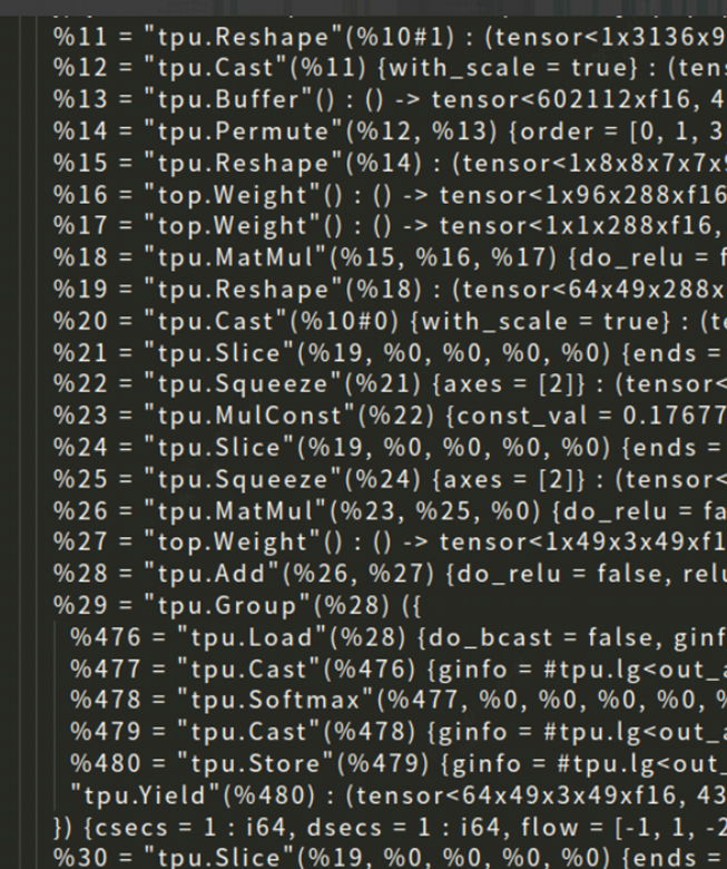
After debugging in tpu-mlir, there are two reasons for the analysis. One is that the local layer of SliceOp does not support 5 dimensions, and the other is that SqueezeOp does not support localgen.
3.1.1.SliceOp#
Code:tpu-mlir/lib/Dialect/Tpu/Interfaces/Common/Slice.cpp
LogicalResult tpu::SliceOp::LocalGenSupport()is used to judge whether the Op can support locallayer.
1 | else if (module::isBM1684XFamily()) { |
It is observed in this code that for the 1684X processor, when num_dims>4, it is directly considered that the local layer is not supported. Here we further improve the logic. In the case of group3d, the 5-dimensional shape will be processed according to [n,c,d,h*w]. So if we only do slice_d at this time, it will not cause data to sort cross the npu, so this situation should also allow the local layer.
1 | if(num_dims == 5){ |
3.1.2.SqueezeOp#
SqueezeOp does not yet support the codegen of the local layer, but ReshapeOp is implemented locally in the backend of 1684X, and SqueezeOp can just use the local layer of ReshapeOp.
First add the localgen general interface definition to Tpu_SqueezeOp in the TpuOps.td:DeclareOpInterfaceMethods<LocalGenInterface, [“LocalGenSupport”]>
On the basis of this interface definition, we need to implement two parts, the interface for calling backend operators and the logic for judging whether local is supported.
Code:tpu-mlir/lib/Dialect/Tpu/Interfaces/BM1684X/Squeeze.cpp
This file implements the interface of SqueezeOp calling the back-end operator of the processor, and we add the interface of codegen_local_bm1684x for it.
1 | void tpu::SqueezeOp::codegen_local_bm1684x(int64_t n_step, int64_t c_step,int64_t h_step, int64_t d_step,int64_t w_step,group_type_t group_type,local_sec_info_t &sec_info) { |
Code:lib/Dialect/Tpu/Interfaces/Common/Squeeze.cpp
This file implements the judgment logic that SqueezeOp supports localgen.
1 | LogicalResult tpu::SqueezeOp::LocalGenSupport() { |
After completing the above optimization, let’s compile the model again to see the effect:
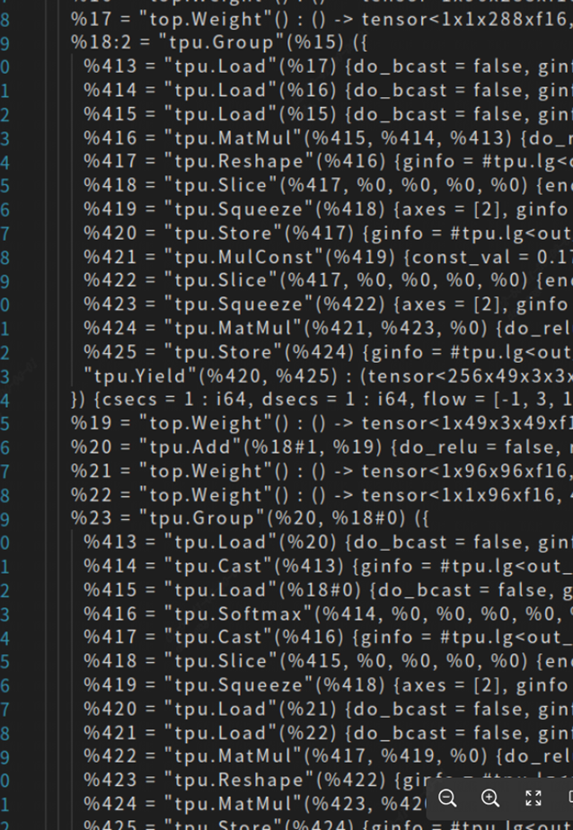
You can see that several global layers have been organized into a group just now.
3.1.3.weight split#
Judging from the effect of the group above, there is still a special situation where AddOp is not grouped with other layers. The reason here is that one input of add is a weight, but tpu-mlir currently does not split the weight, so when the split encounters weight, it is considered that it does not support group. However, for point-to-point operations such as add, if the input is a weight, it can theoretically be split.
In order to support this function, there are many places involved in modification. Interested readers can first understand the process implementation of layer group in tpu-mlir. Related explanation videos are in the open source community:Explain Layer Group incisively
Here is an overview of the ways to support weight split:
Add the allow_split parameter to the top layer WeightOp
2.LocalGenSupport supports point-to-point operations such as add sub mul div max min
Configure allow_split for ops that meet the requirements before doing layer group
If the layer group encounters an input of weight when splitting data, improve the relevant logic
After completing the above optimization, let’s compile the model again to see the effect:
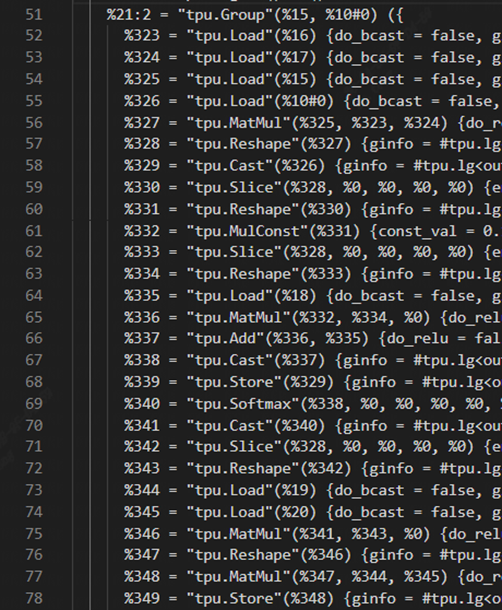
AddOp was also successfully incorporated into the group.
4.Optimization effect#
Use the bmprofile tool to observe the operation of the model again. Compared with before optimization, it saves a lot of time for GDMA handling, and the parallel effect of BDC calculation and GDMA handling data is better.
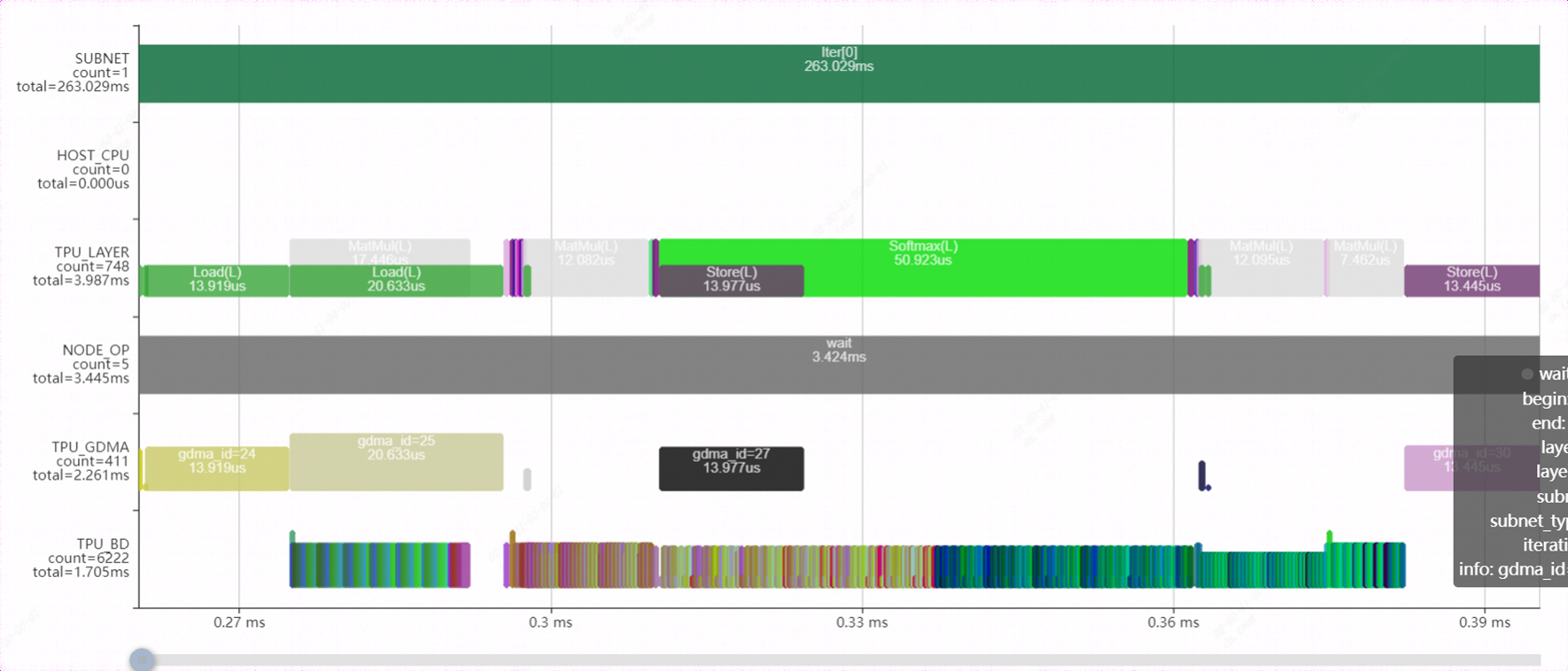
The performance of the model changes:
| FP16 | INT8 | |
|---|---|---|
| before optimization | 7.411ms | 5.505ms |
| after optimization | 3.522ms | 2.228ms |
| Performance increased | 110% | 145% |
Both FP16 model and INT8 model have been greatly improved in running speed on 1684X. So far, the swint optimization work of this stage is completed.
It is hoped that this document can be helpful for other optimization efforts of similar models.